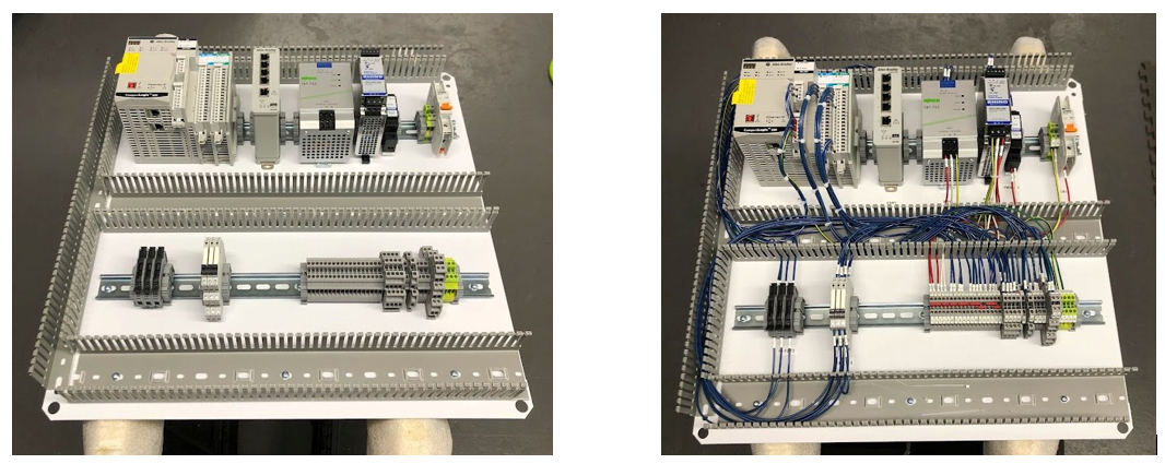
SolidWorks was used for all subpanel and enclosure layouts. For schematic design information, please refer to report (sections 7.1 and 7.2). The electrical schematics were designed using AutoCAD Electrical and can be seen in the appendix of the report.
FANUC 100iB Welding Work Cell (Capstone Project)
This capstone report outlines the process of designing a robotic welding work cell that is used in Rochester Institute of Technology’s Mechanical and Manufacturing Engineering department’s Foundations of Metals Lab to showcase the effects of welding on the mechanical properties of steel.
The work cell is built in the RIT Lab 1190 and integrates the following equipment:
- FANUC 100iB ArcMate Robot with RJ3iB Controller
- Lincoln Electric PowerWave 455M Welder
- Allen Bradley 5380 Series Programmable Logic Controller (PLC)
- Maple Systems CMT3092X Human Machine Interface (HMI)
The report includes the setup procedures that would be required to achieve the same result integrating a FANUC Robot with and Allen Bradley PLC.
Download the full report below:
Below you can also download a PLC to Robot I/O mapping excel sheet that was used for the project. This is an easy way to organize the I/O transferred between Studio 5000 and the Fanuc Robot.
Design Process:
Mechanical Design:
SolidWorks was utilized for all mechanical design. Below you can find the cell layout and fixture design. For more information please download and refer to the report.


Electrical / Hardware Design:


Software Design:
For a more detailed explanation of the software design please refer to report section 10.


The robot in this system is being used as an actuator controlled by the PLC. This allows the PLC to act as the central brain of the system while the robot simply provides status feedback to the PLC.
The setup procedures required for a FANUC robot to be controlled by an external device can be found in section 10.2 of the report.
 HMI System Overview Screen
Many principles from High Performance HMI (book) were used in the design of the HMI including color schemes and the use of an overview screen. For a more detailed description of the HMI see report section 10.4.
Mechanical Build:
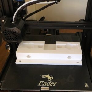
 3D Printed Fixture Prototype

Due to cost of industrial HMI mounts, a $100 podium was purchased from Amazon to be used for the HMI stand. This allows for it to be light and mobile.
Electrical Build:


Conclusion:
This was a large project that started in August of 2022 and was completed in April of 2023. Over this time span I learned more than I ever imagined regarding FANUC robots and robotic welding. Please refer to report section 14 to see some of the lessons I learned throughout the process.
I hope this is helpful to anyone tackling a similar project. Please send me an email or leave a comment about anything you found helpful or I may have missed in the report or any tips for future integration projects.
May 7, 2023 Pete VanCamp Projects
© 2024 petervancamp . All rights reserved.